tiistai 30. maaliskuuta 2021

433 MHz receiver : different protocol for temperature

Continuing previous parts about receiver and transmitter here.

Later addition: you can find sources here.

Previously I was working with controllable outlets, and those are now working nicely; I can control them remotely from home. 

I had planned to integrate wireless temperature sensors operating on same 433 MHz band to the system. Since my system didn't seem to detect them, I had to open one up to see what kind of protocol it was using. It took me a moment to find the data pin (very different transmitter setup on board than with previous remote control), but finally I got data out from it:

Here yellow signal is (unmodulated) transmit output as probed from inside the sensor (well, very first part of it - full sequence is almost a second long) and green is demodulated data as given out by my receiver. You can once again see how noisy data signal from the receiver is when there is no data in (nearby) air.

I would guess that first yellow pulse, on left, should start transmit, and after that data begins. Receiver however doesn't receive first data pulse correctly, but I don't think that is a problem.

Looking more closely, this signal is quite different from signal sent out by outlet remote control. While it used PWM - pulse width modulation - this looks more like PPM - pulse position modulation. The positive pulses are all of same length - about 560us - but low pulse period between them changes, being either 1900us or 3800us (exactly double - not a coincidence!)

Obviously same receiver code that PWM uses doesn't work. So I just wrote parallel system that runs in same interrupt handler, in a way that they both try to figure out signals at same time. 

In the end the logic to parse this PPM signal was something like this: (again, the interrupt handler triggers on both rising and falling edge transitions of signal, so I can process just that transition and exit interrupt handler so it doesn't eat up all the of MCU time)

-On idle, detect hi-to-low signal transition
-On next rising edge, check low period. If it is between (roughly) 1600-2200us, value is zero; if it is between 3500-4100us, it's one; otherwise it's spurious signal and receiver resets to idle.
Note that my choice of short period denoting 0-bit was arbitrary, it could have been inverse, but in this case my guess ended up being correct.
-Check that received high pulse is between 250-750us (due to relatively low resolution of my timer). If it's too short or long, again reset to idle.
-Repeat until 32 bits are received.

As with the PWM receiver, my code is very simple and resets receiver very aggressively to idle. This is again calculated choice; since the input signal is noise for 99+% of the time, I want to spend as little time - and MCU cycles - in the receive interrupt handler as possible. No point waiting to the end of bad data when I can minimize overhead by just rejecting it early.

In the end I receive usually multiple times same value, for example 921EC7A hex, and possibly some other values. At the interrupt handler I just put these received values in a temporary buffer. Sensor sends same value I think 8 times.

As the transmitter sent data for about 800ms total (all 8 repetitions), I set up one-second timeout (from first received value) to trigger final parsing. There I find the value with most copies listed in temporary buffer, and if there are sufficiently many (say, 3 or more of same) I can assume that was the correct value.

Now, to decode this. It helps a bit that sensor also has small display showing the current temperature so I don't have to guess as much.

For temperature of 24,0 C the corresponding received value was 921E0CE .
I got lucky and next reading was 23,9 C - value being 921DF20 .

Note that E0 and DF in middle are exactly one step apart. So I made a guess: lower 8 bits are something else, then follows maybe 11 bits for temperature. Thus decoded values ended up being 480 and 479 - doesn't sound right.

Okay, 9 lowest bits are something else? Bingo. Dropping highest bits, end result 240 and 239 exactly. 

I have no idea what lowest bits could mean. There does not seem to be much of correlation between different readings so temperature in F or humidity are out. Possibly checksum? Humidity might have been nice, but expecting that from cheap sensor would have been too much. So far, I'm happy with just temperature anyway. 

Received successfully.

Edit: Tested again with different type of temperature sensor, and receiver code didn't recognize it. Will need to see how it operates now...




perjantai 26. maaliskuuta 2021

Covid sucks

Continuation of previous post.

The verdict is in, and we, the people, have collectively failed the pandemic response test, and will all die horribly when the next, more serious pandemic hits. Do not have any illusions about it, that new pandemic will happen eventually, and people traveling constantly around the world will only make it worse (and I do realize that everything I say around here makes me a more guilty person here.)  Whether it's more or less dangerous pandemic than current one is anyones guess, but the worse one will be there eventually. Imagine, say, ebola that spreads much, much more easily... (just to name a single example, I know that ebola isn't airborne - at least, it is not at the moment...)

In the meantime, this situation has serious mental health issues. Not being to able to go out normally, to mingle, to speak with others - it appears to have effect even on us introverts. I at least have some verbal contacts due to customers calling me quite often - wife unfortunately isn't as lucky as she has very few people to meet nearby now. And then there are people too to whom this is much, much worse situation to be in.

Not to mention the holiday situation mentioned in that previous post. That's worse. Not being able to properly relax has more serious consequences than I'd have though few years ago and I am starting to feel the results.

I'm starting to feel that I'd be willing to part a far more significant chunk of my account for a nice, safe vacation than I would have been just a few years back. And I'm fairly certain I'm not the only one.

I was hoping we could make a getaway this winter (20-21), or summer at latest. At the moment that is very unlikely, and that alone is already stressing me out. I'd love, love to be able to get vaccinated and start relaxing (even a bit) but so far the situation is bleak. As of writing, they've vaccinated only 10 percent of people here. Not even close to make sufficient coverage, and we (my family) are very, very far down on the list of people prioritized for vaccinations for now. 

This is going to be another long year, I'm afraid.

tiistai 23. helmikuuta 2021

433 MHz transmitter

 Continuing from previous part.

Later addition: you can find sources here.

After I got receiver working - that is, successfully decoding received data - and played a bit with it, it was time to start thinking about transmitter part. I mentioned that I had neglected to order one, so I went looking for one from same large web store. This is where I hit a wall though.

My system is running at about 3.2v. As it turns out, most of the transmitter and receiver modules available are designed or at least sold to be used with Arduino. Therefore most had operating voltage specified to be 5v, with lower limit at 3.5v. Just a few transmitter modules listed 3.0v as lower operating voltage, but these had somewhat worrying review history and I chose not to risk it. (received I had ordered however was specced to work at 3v and had mostly good reviews so no issue there). All in all, no luck.

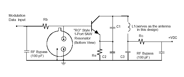
Then I realized I had transmitter already. Hand-held module works with 3v battery, and circuit was relatively simple (very close to this SAW-based one from this site). Main difference is that transmitter I had was passing supply voltage of RF through LED (so when LED is on, RF is on). Easy enough to hack, I thought.

So to testing. Left pin is enable (connected to LED series resistor input), other wires are modulation input from my PCB (and other for scope probing). At lower part of board were 3v supply and ground (battery inputs). I think I could have cut the lower part of board completely off but decided against that.

Getting waveform shape roughly right didn't take long (this I did without transmitter being connected, just looking at generated modulation data from scope), but final tweaks to get it just right for receiver to accept it took a bit longer, mostly getting start and end conditions to match original signal closely enough. That code is fairly trivial, just I/O pin switching and delays of various lengths in between, done with interrupts disabled so that they don't mess with timings. Nothing fancy required here, unlike receiver where a bit of timer trickery was needed to be able to receive data buried in noise as background operation (without interfering with other operations of system)


tiistai 9. helmikuuta 2021

433MHz receiver

Later addition: you can find sources here.

I've been thinking about rudimentary home automation stuff, specifically remotely controlled heating to our cabin. Since it has munincipal water it must remain above freezing temperature, but I'd rather not keep temperature too high (i.e. near comfortable) when we're not there to save electricity, so it's often around +10 degrees C when we go there, and it takes almost a full day for it to warm to more comfortable +20 C. Not great situation.

I already have temperature monitoring in place, with remote reporting (to send an alarm if it gets too cold and needs attention, and also for curiosity monitoring the temperature from home), but controlling heaters - that is, mains voltages - is something I'd rather not fiddle with directly. Although I have no double could make it safe, there's still the issue of pesky insurance claim denials in case something were to happen.

For this purpose I bought a set of remote controlled sockets with sufficient power rating. These are controlled with 433MHz radio signal, so I would have to duplicate signals sent by remote somehow.

I did some web searching and there is actually some articles about this, but they all work on higher level than I'd like. "take Arduino and use this library" is not my thing, really. But those anyway gave me enough pointers to start moving to right direction.

I bought some cheap receivers from certain large internet dealer, but somehow managed forgot to buy transmitters! Damn it. But at least I could start with signal decode part.

This turned out to be slightly more difficult than I though, as either my surroundings is full of 433MHz signals, or these receivers are horribly noisy even when there is no signal around, as presented by this scope capture of actual signal amongst noise. Yellow is output signal of receiver, and small green dots indicate locations where there is end of actual transmitted signal as parsed by (my eventual) system.

Here the original transmitter probing came in handy. I knew that sequence started with short high, followed by fixed length low, followed by actual PWM signal. Getting scope trigger to that reliably wasn't happening, but managed to get it trigger on specific-length "low" often enough to verify that my initial assumptions are correct.

Here's a bit closed look at actual transmitted signal. Start of signal is marked with cursor X1, and end (as I think it is) by X2. At start there's short, 2000us zero pulse, followed by 24-bit PWM coded signal, then possibly "stop bit" of some kind. PWM signals are 380us for "0" and 1200us for "1" (or other way around, I don't really care - I just want to be able to replicate it.)  Next pulse starts always 1500us after previous one, regardless of width of pulse.

I already had thought of the receiver software that could parse this (and other similar signals) with MCU I had ready to go - STM32 series chip (and system) I've used often recently. The idea is this:

Connect receiver output to STM32 I/O pin that can handle external interrupts. I set this line to handle both rising and falling edge interrupts, to stop on both edges. 

I already use the RTC part of STM32 with 32768 Hz clock crystal on it. It has sub-second counter (SSR) which I set to to count to 8192 on every second - 122us per tick. Not great resolution but sufficient here (there is also small power cost involved with higher rates when using battery backup, although it is not important here as I do not need to optimize for that), as "0" and "1" signals have significant time difference. Any hardware timer that allows its internal counter to be read reliably should be fine for this though.

As there is a lot of noise, and thus lots of interrupts here, I designed the interrupt handler to be as short as possible for common case - no recognizable signal, or start of false signal - to reduce time spent there.

When idle, system looks for low period of 1800us or more to start decoding signal. (trigger SSR read on lowering edge, then check elapsed time on rising edge, calculate elapsed time in ticks - obsiously taking care of wraparounds in calculation if there are some). 

After this, on lowering edge SSR is read and time compated; I accept fairly wide range of values; around 200us to 500us as "0" and 900us to 1500us as "1". If timing is out of these bounds, signal is treated as noise and system returns to idle (this large scale is in case I want to use modules with slight timing differences, such as radio-based temperature sensor I haven't tested yet. Also there is the issue of SSR having 122us resolution, so I could expect half of that as average timing error, and also other interrupts that might have blocked this handler temporarily)

Next rising edge is also checked; it must have happened from 1300us to 1700us after before. Again, falling outside this range is noise and system returns to idle, waiting next signal. If timing was correct, system waits for lowering edge, i.e. next bit. After 24 bits data treated as successfully received.

This turned out to be more reliable than I expected, as system received all four identical sequences sent by remote extremely reliably, without any false positives so far. For further proof system might check with majority vote the actual received value, but that has to wait for now.

Next, playing with receivers some more.


lauantai 30. tammikuuta 2021

The Final Walk (part 2)

The day came. I couldn't.

This is continuation for this.

He reached age of 12, which isn't too bad for a dog of his size. In the end it was cancer. He just crashed one day, and quick prognosis from doctor was that he might have maybe few more days, at best.

I wasn't there for his final moments as I was talking care of our (human) kids, but nevertheless, it hurt Bad, Seriuously Bad. 

We have other dog, 5 years old, and he was and still is confused of the situation. At least we have him, and will get another (later), but I won't be looking forward of next time this happens either.

This is part part of the bargain we get. They love us all their life, and we must love them back - and accept that they will leave us so soon.


sunnuntai 18. lokakuuta 2020

Radio headphone teardown

These Philips wireless headphones - model SBC HC8545 specifically - were really nice - when they worked. I bought them maybe 2006 or 2007, and I remember using them quite a lot when our kid was small. Unfortunately they started acting up more and more - specifically headphones did not pick up then wireless signal until maybe after many on-off cycles - until later they just would no longer pick up the signal at all. Bummer, because they offered a lot of freedom and, unlike many headphones, were actually comfortable to wear even with glasses.

They have been sitting on my shelf for a long time now, and since I had some unexpected free time last week I decided to see what's inside.

Headphones had rechargeable batteries (two, AAA size, 1.2v 550 mAh NiMH) and they were charged when on the base station. 

Base has two screw on bottom, and after that top part comes loose - interesting design choice.

RF can has PCB in it, with seemingly just passives and few (likely) transistors in it. U5 at the right is EM78P156 - apparently simple microprocessor. I guess it controls charging, FM transmitter, status LEDs and maybe thing or other thigs. Wires you see at bottom go to charging contacts on top part.

I was looking for chip datecodes until I saw huge date stamp marking on it, placing manufacturing date to november 2006.

Unfortunately for me almost all built-to-price RF circuits are effectively black magic; I can work out how, say, spectrum analyzer RF front end works, as you can clearly see all chips and radio path involved, but these things where oscillators are built with just few passives and maybe a transistor are something I've never managed to grasp.

I thought that is might be possible that the problem might be transmitter or receiver frequency slowly crawling off the spec so receiver could no longer lock on to it.

Headphones opened up. It appears that other cup has mainly power and charging related parts (including batteries), and other has RF parts, and there is nothing tunable on RF side. Copper wire on lower right functions as antenna here. Under the RF cover is RS832U chip; I could not find any information about it. I don't think those blue ones (brown board) are related to RF stuff; brown board is connected to RF board with two pairs of wires, other being power and other audio.

This thing has been sitting on my shelf, unused, for close to ten years. But since I now had it open (previously I had opened only headphone part, finding no adjustments and given up) I thought I might as well try to adjust it, assuming it were the RF being out of tune.

My plan was: I use function generator to enter 1 kHz sine wave to one audio channel, and spectrum analyzer (with very narrow span and resolution bandwidth setting) to find RF carrier at specified frequency (helpfully frequencies - selectable, in case there are multiple devices operating at same area - are listed at bottom of base station) and try adjusting those yellow resistors on transmitter.

But guess what. When I try this, frequency seems to be spot on  (granted, considering that I do not have exact 10MHz reference for analyzer, this isn't exact science) and headphones lock on to signal immediately. 

This was with fresh non-rechargeable AAAs though. I switched back to rechargeable NiMHs (new ones, original ones were totally dead) and no more audio. Hmm. Curious. 

At this point I switched to adjustable desk power supply. Headphones would lock to signal at around 2.5v voltage level, and lose it below that. That's on a bit high side (considering NiMHs are 1.2v nominal), so I now focused to those blue adjustable pots on power board.

After a bit of experimentation I figured out that one very likely adjusts undervoltage sensitivity; I guess that under a specific voltage it cuts power completely from RF board. Other adjusts LED behavior, at which voltage it starts to flash. 

So, new plan: Set my desktop power supply to around 2.3v and start adjusting those two pots so that audio and LED drop out just below that voltage (1.15v being around 10% left on NiMH according to voltage curves, leaving a bit overhead). This turned out to be less than exact science, though, so eventually I ended up just tuning them to "works, plus some" level.

So, now I again have working headphones. If they last for year or so I consider this a big win.

A bit warning if you plan to do this yourself though: Although adjustment takes only a phillips-head screwdriver, those wires inside headphones are very fragile and are torn off the board very easily. Be very very careful with them if you choose to open your headphones up, as soldering them back can be challenging without proper tools.


perjantai 16. lokakuuta 2020

Email (not!)

Last evening, maybe around 20 or 21 clock, I checked my mail (mainly to get rid of spam, I try to not reply but to shortest and clearest messages on evenings) and tried to send a quick reply, which failed. Server had went down for whatever reason (probably server was already down by that time; laptop very likely had loaded those few messages on standby earlier on evening)

Now, some 16 hours later the email is still down.

You never realize how often you need something until it's gone - albeit this is but temporary problem, but nevertheless. 

"Good, new software build works, I'll just email the details [to a guy] for testing... awwdamnit"

"So I'll just open the mail which had device serial  numbers I need to...crap"

And so on. Over and over again today.

(side note; I absolutely hate Slack (which I only used briefly for a side project once, fortunately) and other similar online messenger type software for work; there is implicit requirement of responding right now which is really disturbing for my work flow)

Not a rant (above tangent aside). It's just a bummer not being able to do so many things due to old, but apparently all-so-critical tool being unavailable.